Shure ULX Wireless System User Manual
Browse online or download User Manual for Musical Instruments Shure ULX Wireless System. Shure ULX Wireless System User Manual
- Page / 28
- Table of contents
- TROUBLESHOOTING
- BOOKMARKS
- ULX Wireless System 1
- User Guide 1
- CONTENTS 2
- FIGURE 1 3
- Front Panel 4
- Rear Panel 4
- SINGLE SYSTEM SETUP 6
- Receiver Connections 6
- Turning the Receiver On 7
- TRANSMITTER SETUP 11
- ULX1 Bodypack Connections 11
- Turning the Transmitter On 11
- ULXS4 ULXP4 13
- SYSTEM OPERATION 14
- Transmitter Gain Adjustment 14
- Unlocking the Receiver 18
- Locking the Receiver 18
- RECEIVER INSTALLATION 19
- SPECIFICATIONS 21
- ULX1 Transmitter Output 22
- ULX2 Transmitter Input 22
- ULX2 Transmitter Output 22
- CERTIFICATION 23
- REPLACEMENT PARTS 23
- FURNISHED ACCESSORIES 24
- OPTIONAL ACCESSORIES 24
- BATTERY LIFE 24
- TROUBLESHOOTING 25
- IMPORTANT! 26
- LIMITED TWO-YEAR WARRANTY 27
- DECLARATION OF CONFORMITY 27
Summary of Contents
27EN8732E (Rev. 8) Printed in U.S.A.©2006, Shure IncorporatedULX Wireless System User Guide
10ULX2 TRANSMITTER FEATURES AND CONTROLSFIGURE 19 Grille. Protects the microphone cartridge and helps reduce breath sounds and wind noise. The grilles
11TRANSMITTER SETUP Transmitter Battery Installation Open the battery cover and insert a fresh 9V alkaline or lithium battery, as shown in Figure 20.
12Checking Transmitter Battery Power With the transmitter turned on, observe the Battery Level icon on the display. The number of shaded bars on the i
134. Press the SET button to advance to the desired Channel number, as shown in Figure 27. FIGURE 27 To reverse the direction of the Group or Channel
14SYSTEM OPERATION Speak into the microphone or play your instrument. If your audio system is properly set and functioning, you should hear the sound
15Locking Transmitter Frequency Settings Refer to Figure 33. Slide the transmitter power switch to the OFF position and wait for the display light to
16Locking the Power On/Off Switch Turn the transmitter on by sliding the power switch to the ON position. While holding down the SET button, press and
17ADVANCED PROGRAMMING MODE (ULXP4 MODELS ONLY) Scanning Frequency Groups Hold down the receiver SET button and press the MODE button once. The words
182. Rotate the control knob. The new Squelch setting will appear on the display, as shown in Figure 42. FIGURE 42 3. To accept the new Squelch valu
19RECEIVER INSTALLATION Table Mounting the ULXS4 Standard Receiver To mount a ULXS4 Standard receiver on a table or other horizontal surface, attach t
2CONTENTSULX SYSTEM COMPONENTS ...
20Rack Mounting Dual ULXP4 Receivers Align the receivers side by side so that the front panels both face the same direction. Place the supplied stradd
21TIPS FOR ACHIEVING OPTIMUM PERFORMANCE Maintain a line of sight between the transmitter and receiver antennas. Avoid placing transmitter and receive
22ULX1 Transmitter Output Actual Impedance: 50 Ω Nominal Output Level: 20 mW Maximum Output Level: 30 mW Pin Assignments: Shell = Ground Center = Sign
23Ultimate Quieting (reference ±38 kHz deviation) >105 dB, A-weighted System Distortion (reference ±38 kHz deviation, 1 kHz modulation) 0.3% total
24Belt Clip . . . . . . . . . . . . . . . . . . . . . . . . . . . . . . . . . . . . . . . . . . . . . . . . . . . . . . . . . . . . . . . . . . . . .
25NOTE: Batteries stored for more than a year or stored in excessively hot environments may experience a higher failure rate.NOTE: When using recha
26PROBLEMINDICATOR STATUSSOLUTIONSRECEIVERULXS4 ULX4PTRANSMITTERULX1 ULX2Sound level from the receiver is different from that of a cabled
27LIMITED TWO-YEAR WARRANTY Shure Incorporated (“Shure”) hereby warrants that this product will be free from defects in materials and workmanship for
28SHURE Incorporated Web Address: http://www.shure.com United States, Canada Latin America, Caribbean: 5800 W. Touhy Avenue, Niles, IL 60714-4608, U.
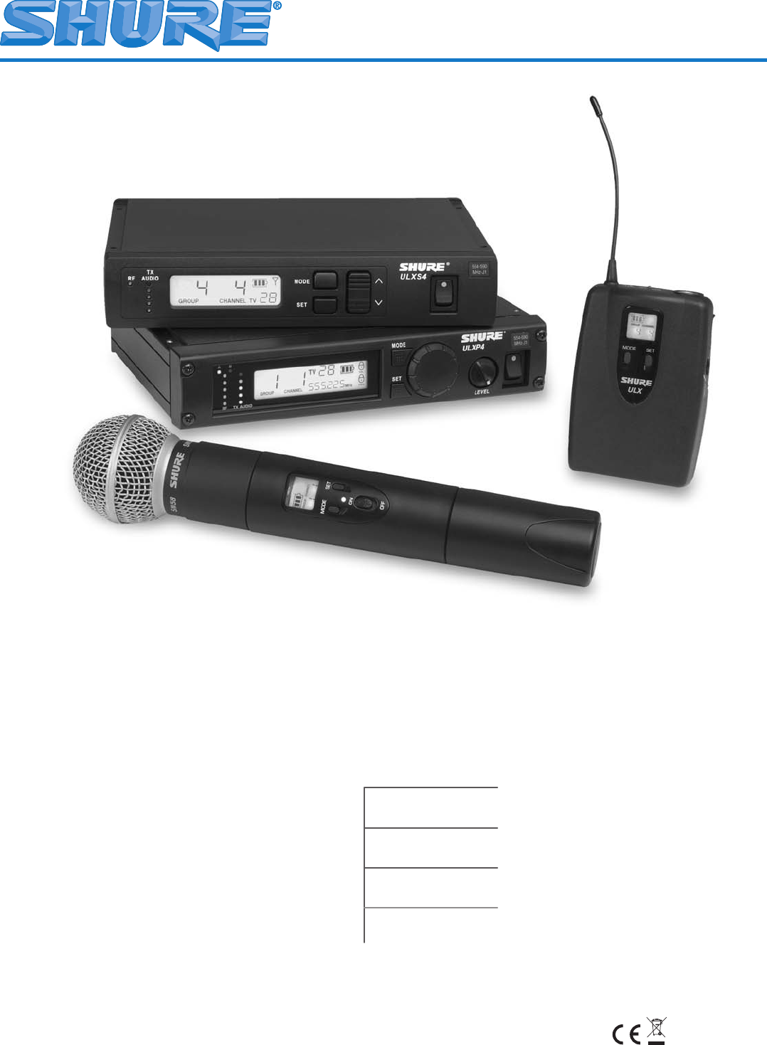
3ULX SYSTEM COMPONENTSFIGURE 1 Each Shure ULX® Wireless System includes the following components, as shown in Figure 1: ULX1 Body-Pack Transmitter wit
4ULXS4 STANDARD RECEIVER FEATURES AND CONTROLSFIGURE 2 Front Panel 1. “RF” Indicator. Glows green to indicate presence of received Radio Frequency (R
5ULXP4 PROFESSIONAL RECEIVER FEATURES AND CONTROLSFIGURE 3 Front Panel Receiving Antenna Indicators. One of these amber LEDs will glow , depending on
6SINGLE SYSTEM SETUP Receiver Connections NOTE: If you are installing multiple ULXP4 Professional systems, or systems with multiple ULXP4 receivers,
74. If the receiver XLR output is used, make sure the MIC/LINE switch setting matches the input requirements of the mixer or amplier, as shown in F
8Changing the Receiver Group Setting 1. Press the MODE button twice. The word GROUP will ash on the display, as shown in Figure 12. FIGURE 12 2. P
9ULX1 TRANSMITTER FEATURES AND CONTROLS FIGURE 18 Antenna. A exible 1/4 wave antenna is permanently attached to the top of the ULX1 transmitter. Inpu
Related products and manuals for Musical Instruments Shure ULX Wireless System


 (16 pages)
 (23 pages)
© 2020, manymanuals.com. All rights reserved. | 0.088 s |
 Manymanuals.com
 Manymanuals.de
 Manymanuals.fr
 Manymanuals.it
 Manymanuals.pl
 Manymanuals.cz
 Manymanuals.es
 Manymanuals-pt.com
Comments to this Manuals